After the first breadboard and voltage-divider work, ESAP robotics moved from reading signals to producing motion. The main thread through these tasks was actuation: making LEDs fade with PWM, driving servos smoothly, switching solenoids through MOSFETs, and reading digital inputs reliably enough to use them in a physical system.
The first useful mental model was duty cycle. I wrote code where a 500 Hz LED signal had a 2 ms period, so a 25% duty cycle meant about 500 microseconds on and the rest off. Then I used the ESP32 LEDC library with 12-bit resolution, writing values up to 4095 to make an LED fade in and out like a heartbeat. The code treated brightness as a value that could be shaped over time, not just on or off:
ledcWrite(LED_PIN, 4095 * (max_intensity * (i / (time_to_increase * 500))));
delay(2);
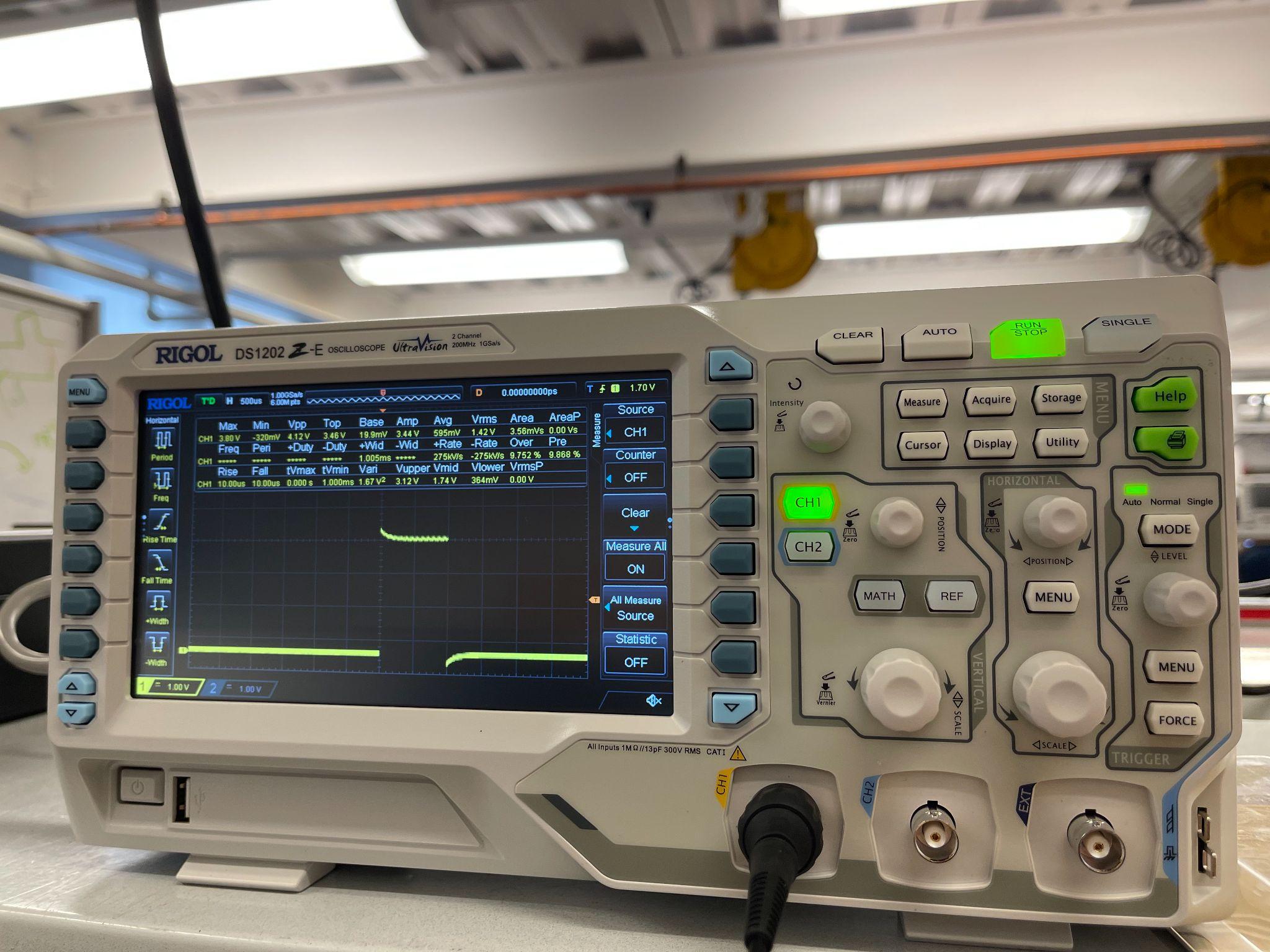
That carried directly into servos. The target signal was a 50 Hz PWM waveform with a 1 ms on-pulse, which is a 5% duty cycle. We checked that on the oscilloscope before connecting the servo, because the waveform matters: a servo is not being powered by the signal pin, it is interpreting pulse width as a position command while taking real power from a separate 5 V supply.
Once the basic PWM worked, I wrote a smoother movement routine instead of only jumping between two positions. The servo still moves as fast as it physically can when given a target, so the code had to break a large motion into smaller steps over a requested time interval. I also tested a potentiometer-controlled version, mapping the analog value to the servo range. That version had noise, which I noted may have come from calling my own sweep function instead of writing more directly to the PWM output.
Solenoids were the next actuator type. The important difference was that a solenoid draws much more current than a microcontroller GPIO pin can safely supply, so the microcontroller controlled a MOSFET instead of the solenoid directly. For an early xylophone concept, we planned one MOSFET and one solenoid for each bar, with port expanders helping the microcontroller coordinate many outputs. The mechanical idea was a seesaw-style linkage that converted the solenoid's linear pull into mallet rotation, with a spring providing a fast release.
The solenoid testing made the power side more concrete. We first debugged the MOSFET circuit with an LED and resistor, then replaced the LED with the solenoid. Adding more current made the solenoid faster; I estimated the speed increase from 12 V to 16 V at about 35%. A resistor-heavy version did not work well because the resistance was still too high, and a 1.5 kOhm resistor in parallel was functionally useless because it drew negligible current compared with the solenoid path.
The digital input work added the input side of the same problem. I wired a switch to GPIO04 with INPUT_PULLUP, printed whenever the state changed, and then wrote a debounce routine so that contact bounce would not appear as multiple intentional presses. The fastest manual test I recorded was about 300 ms for two presses, which was a useful reminder that software timing has to separate real events from electrical noise.
The main lesson from this set of tasks was that robotics actuation is not only "make the motor move." PWM settings, power delivery, current limits, mechanical release, input noise, and timing jitter all affect whether the robot can do the real task. A simple single-actuator demo is useful, but the real engineering starts when the electronics, code timing, and mechanism have to agree at the same time.